FlowTools for Autodesk® Inventor® Documentation
FlowTools Commands
Printing Tools
 Print Plus (Drawings)
Print to multiple printers and multiple papersizes at once. Printing profiles may be setup to automatically print different sheet sizes to specific printers using preset settings such as color, orientation and scale. For example a profile may be set up to print each sheet to a plotter or printer depending on the size of the sheet. Or another profile may be setup to print all sheet sizes to a printer on letter size paper to fit.
Assembly Tools
 Move to Origin
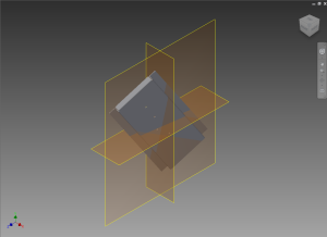
Move and align the selected components to the assembly origin planes.
![]()
 Ground to Origin
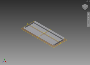
Move and ground the selected components to the assembly origin planes.
![]()
 Origin Constrain
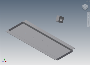
Move and constrain the selected components to the assembly origin planes.
![]()
Note: Only available if activated.
 Constrain to Component Orgin
Move, align and constrain a component to the origin of a target component in an assembly.
![]()
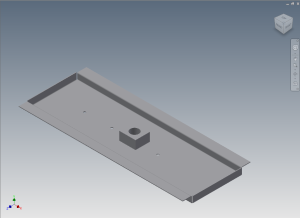
Note: Only available if activated.
Drawing Tools
 Insert Dimension Table
Inserts a static dimenstion table into the drawing using values from parameters specified with a prefix in the files selected. Parameters are selected by a prefix and the column headers uses the dimension name (minus the prefix optionally) for the column label. Not including a prefix will import all parameters in the part for the table.
First setup the part file with importable parameters. The easiest way to get the desired dimensions are to create sketches with driven dimensions. Any parameter can be used. The parameter name must be prefixed the a prefix used to delineat importable dimensions.
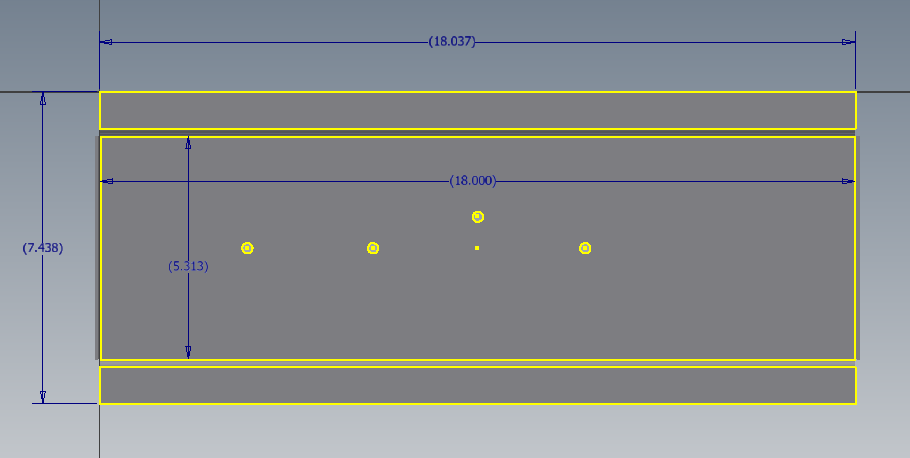
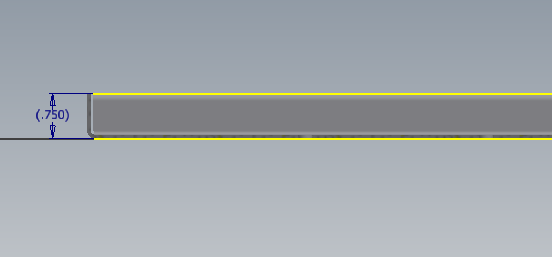
Next rename the dimensions with the desired prefix and label.
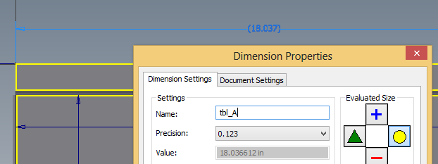
Do this for each part that you want to include in the dimension table. Be sure to consistently name the dimensions in each part. If using a seperate sketch for the dimensions the visibility of the sketch can be turned off. Multiple sketches may be used. Existing parameters may be renamed for use as well.
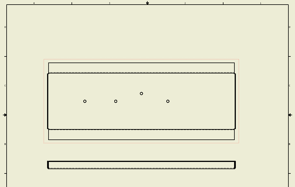
Next place one of the parts in a drawing as the base view along with any other views.
On the Annotate ribbon click on the Insert Dimension Table icon ![]() . Options for the inserted table will appear.
. Options for the inserted table will appear.
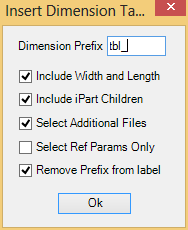
Enter the prefixed used in the Dimension Prefix field. If the field is left blank all parameters will be used to populate to table.
If the part has a flat pattern the checking the box to include the Width and Length will insert the values into columns at the end of the table.
If the part is an iPartFactory checking the box to include the iPart Children will insert rows for each child in the factory.
Checking the Select Addtional Files will open a file selection dialog to select more documents for rows.
Checking the Select Ref Params Only will only include reference parameters in table. (Useful if you don't use a prefix to only include reference parameters).
If the prefix should not be included in the column header label check the box Remove Prefix from label.
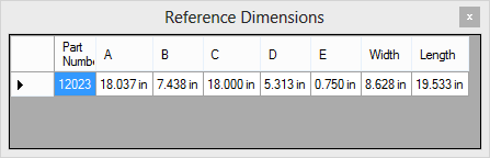
After clicking ok, the parts will be scanned and a preview table will be displayed. When the preview is closed the table will be generated and inserted into the lower left corner of the drawing.
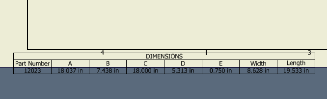
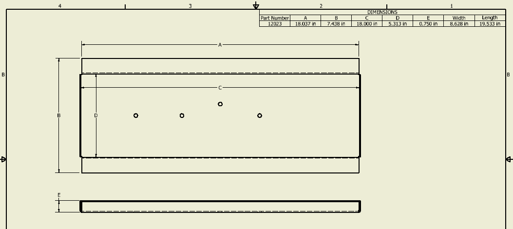
Move the table to the desired location on the drawing. The table is static. It will need to be re-inserted if any values change on the parts. The table can also be manually modified.
 Sheet Namer
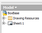
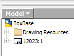
This command will rename all the sheets in the current drawing document to the value of the Part Number iProperty of the part shown in the base view of the sheet.
![]()
Parametric Tools
 Parameter Editor
The parameter editor aids in editing parameter expressions in a larger more user friendly editor. The editor features a syntax highlighted editor that can display long complex expression in a clearly visible area. Portions of an expression can be examined while editing. Parameter values can be seen, portions of an expression can be highlighted and the value seen.
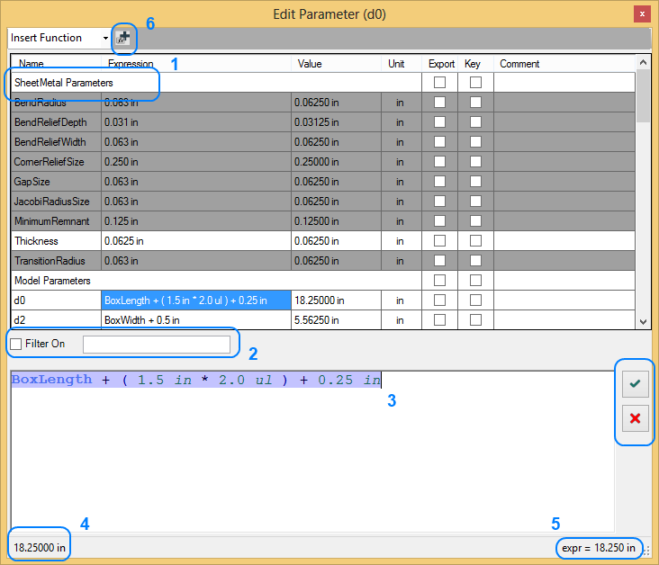
Elements of the Parameter Editor
- Section Headers. Click to collapse a section.
- Parameter Filter. If checked the parameter list is filtered on the text entered in the field.
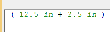
- Parameter Expression Editor. Editor area for the expression. Features syntax highlighting for expression elements. Correct parameter names are highlighted. If the expression has an error the text will highlight red.
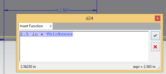
- Running value of the expression. Updates as expressions are entered.
- Expression evaluator. Will display the value of the highlighted portion of an expression. Position the on a parameter name and it's value will display.
- Add new parameters. Multiple parameters can be added at once by seperating the names with a comma.
- Accept / Cancel the expression in the editor.
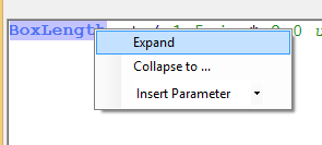
Right mouse clicking in the expression edit area will display a context menu with the items Expand, Collapse to..., and Insert Parameter.
Right clicking on a higlighted parameter name and selecting Expand will replace the parameter name with the expression of the parameter.
![]()
Right clicking on a hightlighted portion of the expression and selecting Collapse to... will replace the selection with a new parameter. A dialog will appear giving you the option to name the parameter.
Right clicking and selecting Insert Parameter allows you to insert an existing parameter from the dropdown menu.
Selecting on the expression in will set the edit are to the expression for editing. The current parameter being edited will be displayed in the title bar.
Select a parameter name while editing will insert that parameter name into the expression at the cursors postion.
Parameters can be renamed, added, deleted, and modify the units and comments.
Extended Sketch Dimension Edit
Right click on a dimension in a sketch and select Extended Edit to edit the dimension using the expression editor from the parameter edit form.
Quick Parameters
A dockable pane that parameters can be added to for quick access.
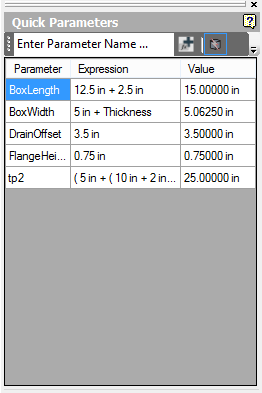
Enter the name of the parameter into the text box then click the ![]() button. The parameter will be added to the list.
button. The parameter will be added to the list.
Multiple parameters can be added by entering a wild card text fragment (i.e. "Box*"). All parameters matching the text will be added to the list.
Parameter expressions can be modified in the pane without opening the parameter editor. Double clicking on a parameter expression will open the expression in an expression editor for modifying.
Select a row and right click to remove one row or all rows.
Rows added to the list are saved and will appear in the list when the document is reopened.
The Quick Parameters feature is useful for displaying the critical parameters to be changed on templates.
Note: If not activated a maximum of 5 parameters can be added to the list.
Sheet Metal Tools
 Flat Pattern Export
Save flat patterns to a folder at a specified format. Flat patterns can be saved individually at the part level or en masse from an assembly or drawing document.
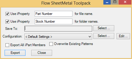
If use iProperty for file name is checked, the iProperty value will be used for naming the exported files. This option must be used when exporting from an assembly or drawing. The default property used is the Part Number. This cannot be changed if the Sheet Metal Pack is not activated.
If used iProperty for folder names the exported flat patterns will be saved in sub folders using the iProperty value for folder names. This defaults to the Stock Number iProperty. This option is unavailable if the Sheet Metal Pack is not activated.
'Save to' specifies target folder to save patterns to. If this value is blank the current working folder of the file opened is used as the save to folder.
The output configuration can be preset to named settings and are available from the configuration drop down.
Export all iPart Members will export all the children of an iPart factory if there an iPart is open or referenced in the assembly or drawing.
Overwrite Existing Patterns will write over any patterns of the same name in the Save To folder. If unchecked a warning will be displayed an existing flat pattern exists in the Save To folder.
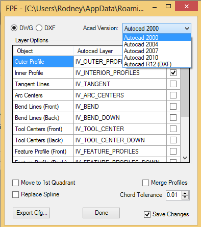
Files can be saved in dwg or dxf format to the specified Autocad version. Layers to be exported can be select or deslected from the list.
Clicking Export Cfg will save the options to a new settings file. The new settings file will be available in the list of configurations.
Note: If not activated a maximum of 5 patterns will be exported from drawings and assemblies.